
Custom 3D Modeling for 3D Printing
Two Interfaces, One Part Between Them.
An adapter exists because two things were never designed to meet, which makes it an interface problem before it is a shape problem. The part is only as good as its understanding of both ends. For a thread we need the standard and size, or a measurement of major diameter and pitch. For a shaft, the diameter and whether the fit is slip or press. For a flange, the bolt circle and the face geometry. For a hose, the outside diameter and the clamp style. Photograph each end with a rule beside it, and say which end carries the load and which one only has to stay put. Where an end is a standard part, name it — that is faster and more reliable than measuring it.
An adapter is defined by its two ends
Most adapters are small, and most of them fail at one end. Not because the shape was hard, but because one end was described from memory instead of measured. A thread called out one size small, a hose barb measured across the outside instead of the bore, a bolt circle measured between adjacent holes instead of across the diameter: each of those produces a part that looks right and assembles nowhere.
So the brief is built end by end. For each end we want to know three things: what it connects to, how that connection is secured, and what the load is. A hose clamp, an O-ring, a thread and a press fit all resist force in different ways, and the geometry of the joint — the length of engagement, the wall around a bore, the lip that stops a hose sliding past — is chosen from that answer.
What to measure at each end
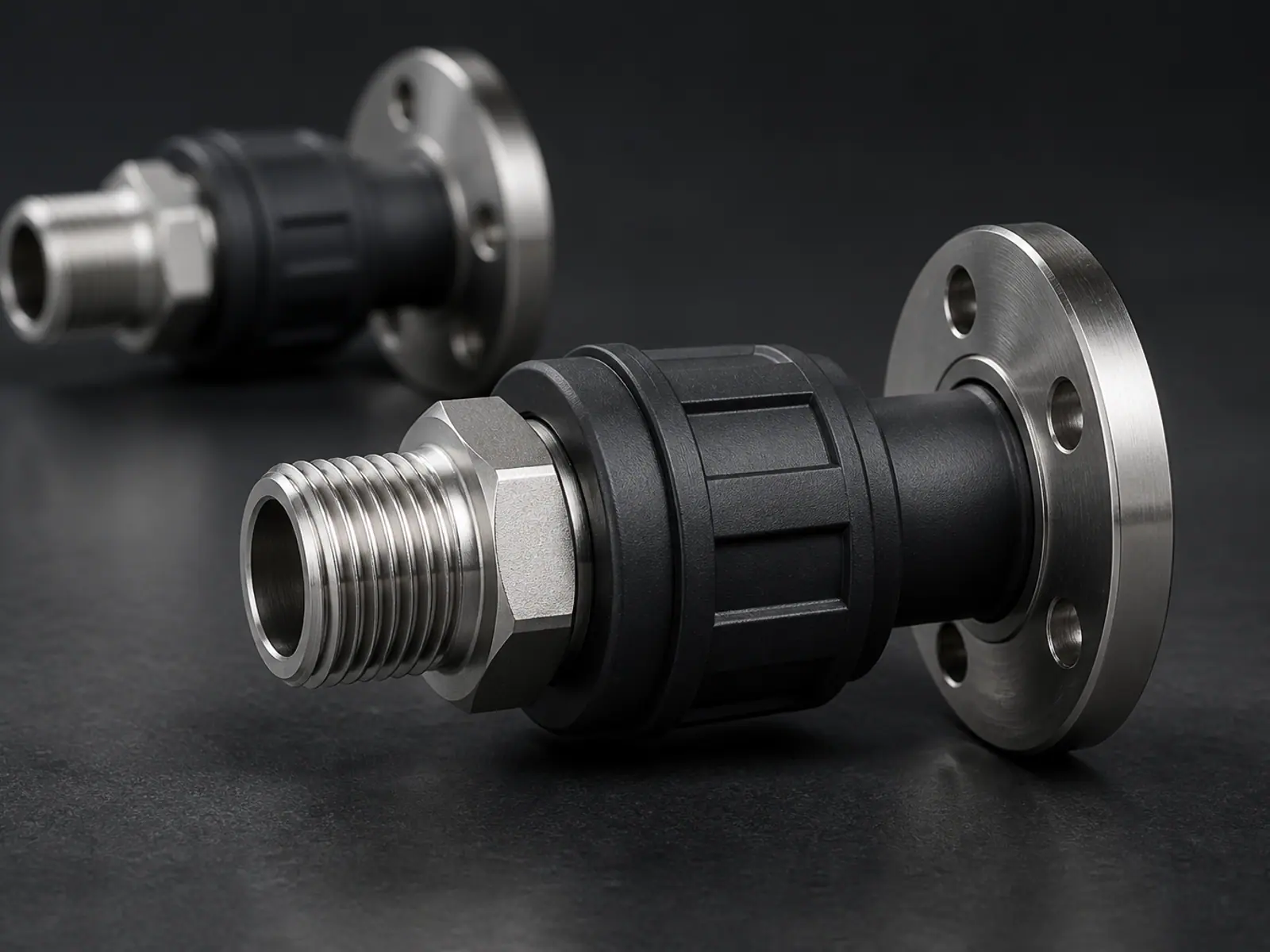
- Threads: the standard and nominal size if it is known, otherwise the outside diameter and the pitch, measured over several threads and divided.
- Shafts and bores: the diameter, the depth of engagement, and whether the fit is slip, snug or press.
- Flanges: bolt circle diameter, hole count and hole size, plus the face width that has to sit flat against something.
- Hose and tube: outside diameter, wall thickness, and how it is held — clamp, barb, push-fit or compression.
- Any seal: the seat diameter, the width of the groove, and whether a soft seal is used at all.
- The space around the joint, including how far each side can move when the adapter is tightened.
How the two ends get joined in the middle
The middle of the adapter is where the design freedom is, and it is also where the part either carries the load comfortably or concentrates it in one thin section. The body is kept as straight as the existing centre lines allow, since every change of direction adds a bending moment and a corner that has to be filleted.
End types and what each one needs
| End type | What we need | What it changes in the design |
|---|---|---|
| Thread | Standard and nominal size, or outside diameter and pitch | Printed threads are usually replaced by a pocket for a metal insert or a nut |
| Shaft or bore | Diameter, engagement length, and slip or press fit | Bore roundness depends on print orientation, which is chosen before modelling ends |
| Flange | Bolt circle diameter, hole count and size, face width | A recess for a soft gasket is added where the joint has to seal |
| Hose or tube | Outside diameter, wall thickness, clamp style | Barb shape and a stop ring so the hose cannot slide further on |
Sealing, threads and printed accuracy
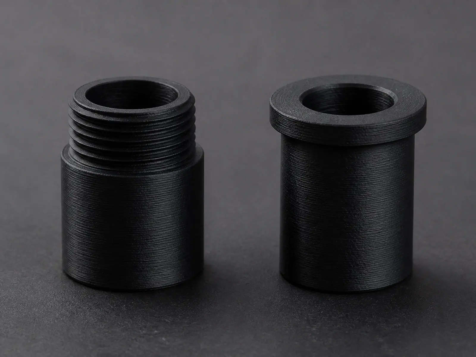
A printed part is not a machined part, and an adapter is the one job type where that difference shows up immediately. Printed bores come out slightly under size, printed threads are coarse and rarely seal, and a wall that is thin at the end of a bore will crack when something is tightened into it. Each of those has a standard way around it.
- Metal insert or nut pocket for any thread that will be used more than a few times, rather than a directly printed thread.
- Bore diameter set with a small allowance, then drilled or reamed to final size where the fit is critical.
- Wall thickness around a press fit increased, because hoop stress is what splits a printed bore.
- Gasket grooves designed with a defined squeeze, so a soft seal is compressed rather than simply trapped.
- Orientation chosen so the bore is printed round and the layer lines do not run across the sealing face.
- A flat, machinable face left at each end where the adapter has to seat against something solid.
Model, test fit, then finalise
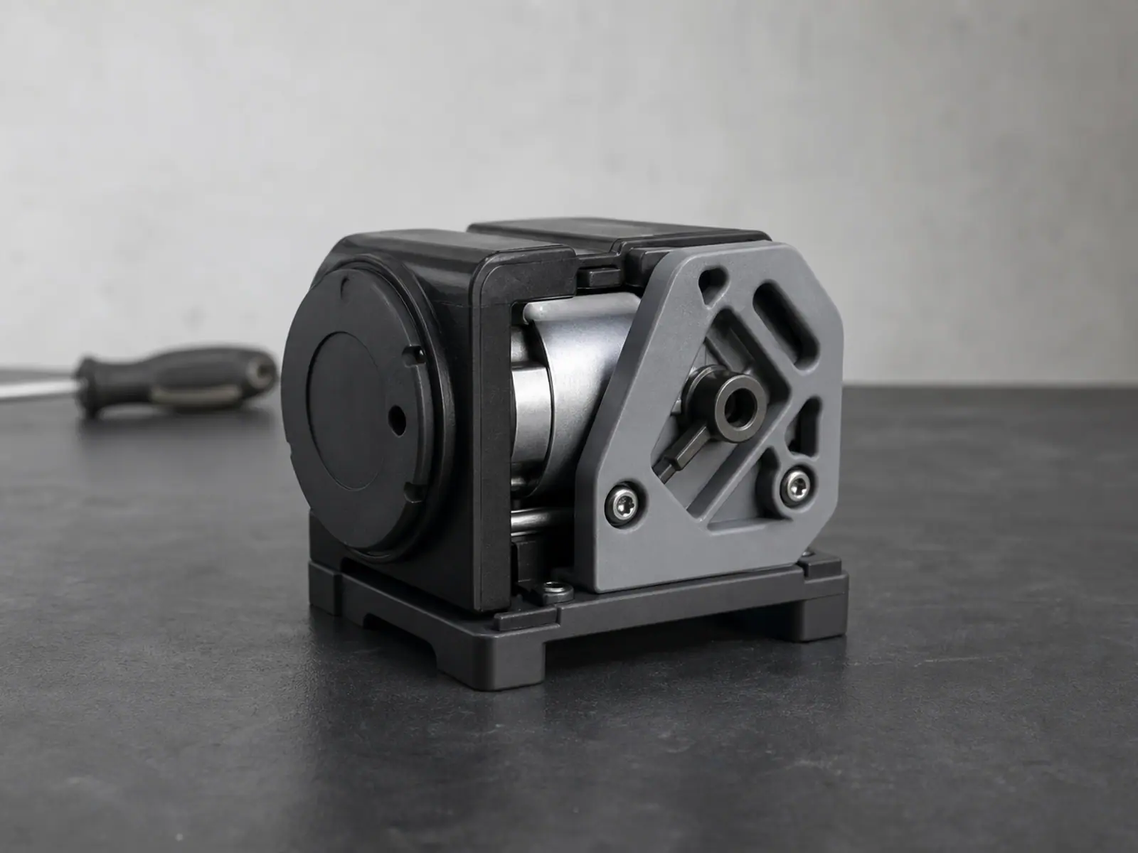
Adapters are checked against the real thing before the file is closed. Where both ends are available, a prototype print is the fastest way to find the one dimension that is off, and it is a short trip from there to the final model. Where only one end can be tested, we mark the untested end clearly in the handover notes so you know which measurement to confirm.
The deliverable is adapter CAD with both ends modelled as separate features, so either interface can be adjusted without redrawing the body, plus a print-ready STL or 3MF in the recommended orientation. Editable CAD is available when the scope includes it, and prototype printing is an optional step after the model is reviewed.
Use a thread gauge or a known screw to identify a thread rather than a ruler. Half a millimetre of error on a pitch is the difference between an adapter that threads on and one that cross-threads.
Related services
Frequently asked questions
Frequently asked questions
How do I measure a thread for an adapter?
Can a printed adapter hold pressure or seal?
Should the thread be printed or use an insert?
What if I can only measure one end?
How do I measure a bolt circle on a flange?
Can you design an adapter between two standard fittings?
Two Interfaces, One Part Between Them.
An adapter exists because two things were never designed to meet, which makes it an interface problem before it is a shape problem. The part is only as good as its understanding of both ends. For a thread we need the standard and size, or a measurement of major diameter and pitch. For a shaft, the diameter and whether the fit is slip or press. For a flange, the bolt circle and the face geometry. For a hose, the outside diameter and the clamp style. Photograph each end with a rule beside it, and say which end carries the load and which one only has to stay put. Where an end is a standard part, name it — that is faster and more reliable than measuring it.