
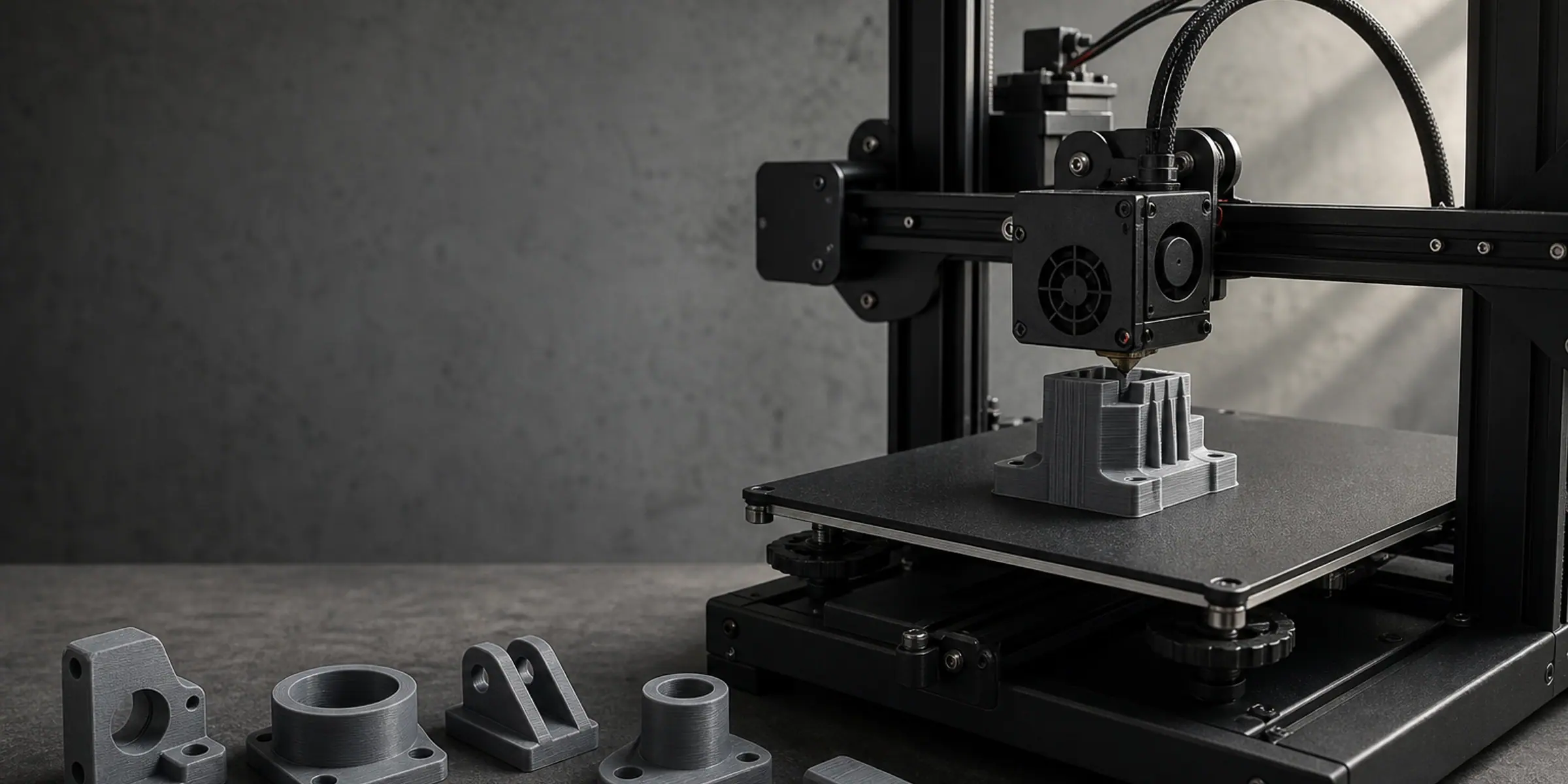
Custom 3D Modeling for 3D Printing
Custom 3D models that start from what you already have.
You do not need a CAD file, a scanner or design software to start. Send photographs of the part, a sketch with a few dimensions, a broken original, or an STL that will not slice, and we turn it into a solid model a printer can actually produce: real wall thickness, printable overhangs, clearances that close when the plastic cools, and a print orientation chosen for the loads the part will see. This page is the hub for all of our modelling work. The eight job types below are the routes in, each with its own detail page, and if you are not sure which one applies to you, describe the part and we will point you at the right one.
Modelling for the printer is not modelling for the screen
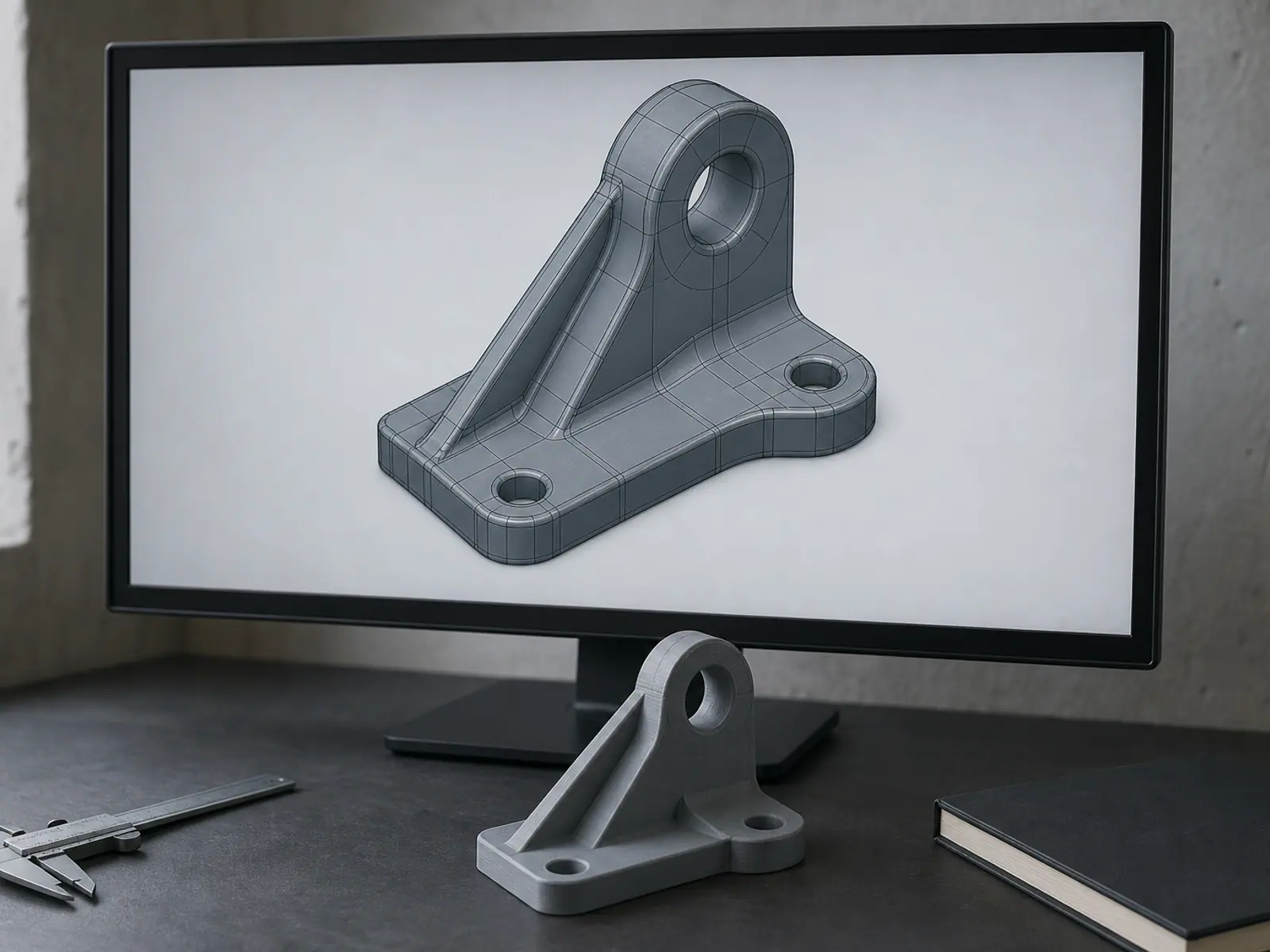
A render only has to look correct from one camera angle. A printed part has to exist. Every wall has to be thick enough to be extruded, every overhang has to be printable or supported, and every surface that touches another part has to leave a gap that closes as the material cools and shrinks. That is why we model in solids rather than surfaces: the file you receive has real wall thickness, real inside corners and a real section through the part, not a shell that looks convincing in a viewer.
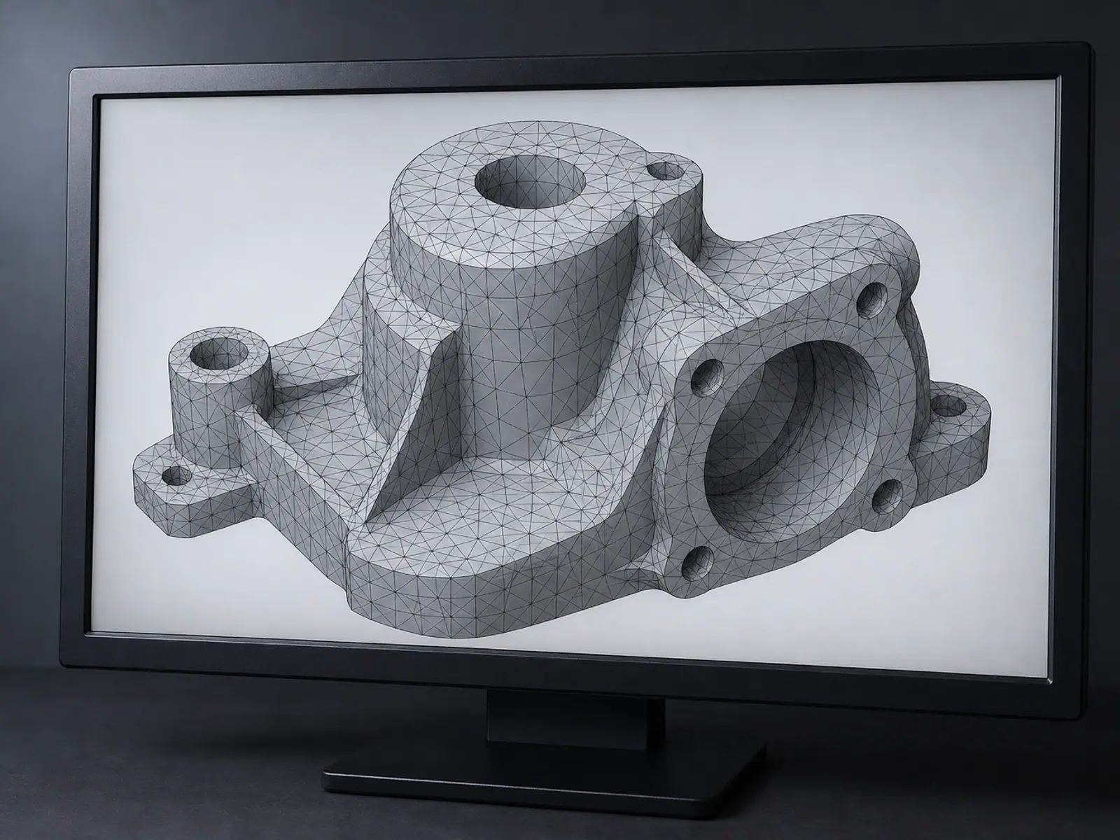
This is also why models that came out of a sculpting tool or a photo-to-mesh app usually fail here. They can look watertight and still be unprintable in practice — a wall that is solid on the outside and hollow in the middle, a clearance of a tenth of a millimetre where the printer needs four, a load path that runs straight across the layer lines. A model is not finished when it renders. It is finished when it prints, fits and holds.
- Wall thickness is set by the nozzle, the material and the load the wall carries — not by what the model looks like.
- Overhang angle depends on cooling: the angle that prints cleanly on one machine is a drooping mess on another, so the process is chosen before the geometry is fixed.
- Print orientation decides strength, because a printed part is weakest between its layers. We orient the part so the load does not pull the layers apart.
- Assembly clearance has to match the real accuracy of the printer, which is not the ideal number written in the CAD file.
- Fillets and radii at inside corners cost nothing to model and remove the sharp stress raisers where printed parts usually crack.
A model is finished when the printed part fits and holds — not when it renders.
Five checks every model passes before it leaves here
Printability review is part of the modelling job, not a separate service you have to remember to buy. Nobody should find out that a wall is too thin when the printer is already running.

- Wall thickness and minimum feature check against the process you will actually use.
- Overhang and bridge review: we mark where supports are needed and where they will leave a mark on a visible surface.
- Orientation and load direction: the part is placed so the weakest direction is not the loaded one.
- Fit check on every interface dimension, with clearance added for the printer's real tolerance rather than an ideal one.
- File check: watertight solid, correct units, scale at 1:1, exported as STL, STEP or 3MF depending on what you need next.
The eight jobs this hub covers
Everything below is the same discipline applied to a different starting point, and each one has its own page. If the only thing you have is a camera, cad from photo explains how to photograph a part so that it can be modelled; if the part lives on paper, cad from sketch covers what a sketch has to show. custom stl design is for parts that do not exist yet, stl repair service is for meshes that will not slice, and the three interface jobs — electronics enclosure design, custom bracket design and adapter design — cover the case, the mount and the joint between two existing fittings.
- CAD from photo — when the only thing you have is a phone camera and the part in your hand.
- CAD from sketch — when the idea exists on paper with a few dimensions written on it.
- Custom STL design — when the part does not exist yet and has to be designed for printing.
- STL repair service — when a mesh has holes, flipped normals or walls with no thickness.
- Electronics enclosure design — when a board or an assembly needs a case that actually fits it.
- Custom bracket design — when something has to be mounted and carry a load.
- Adapter design — when two interfaces were never meant to meet.
- Replacement part CAD and reverse engineering — when the part is real but no longer available.
What to send, and what comes back
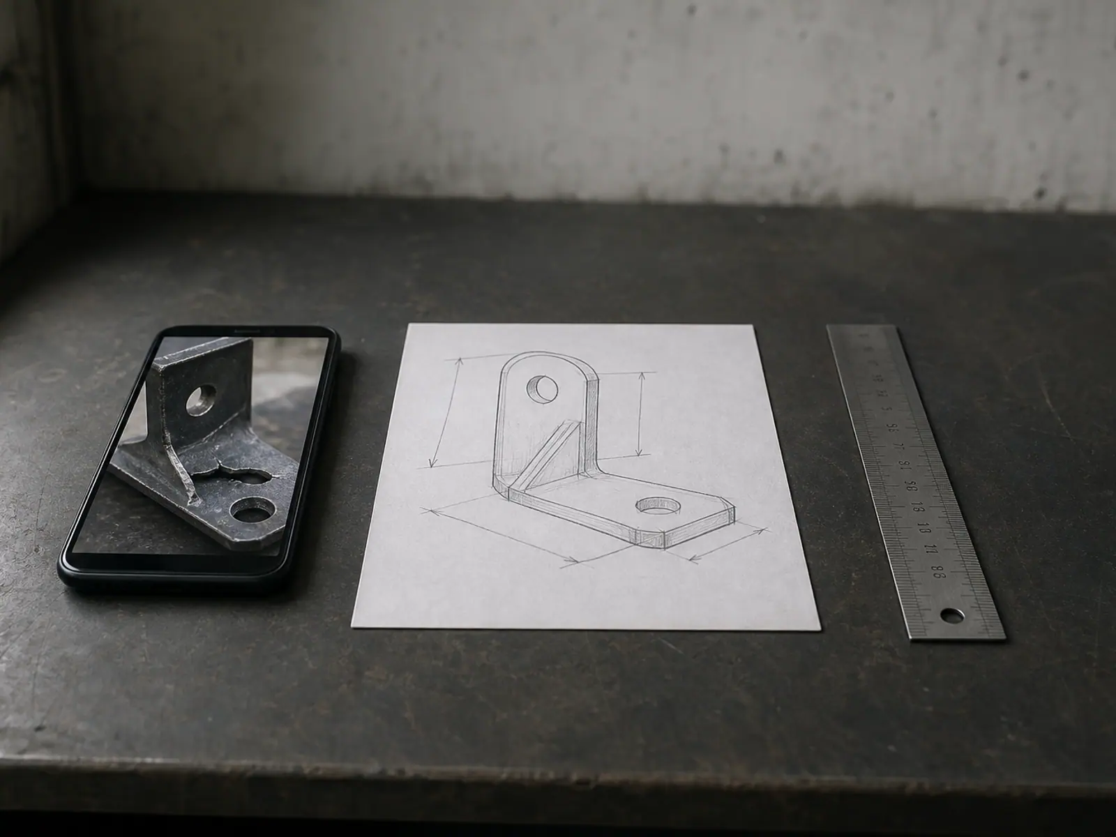
Send whatever you have in the state it is in: photographs from three angles with something in the frame for scale, a sketch carrying the dimensions you could measure, the broken part with every fragment, or the file that will not slice. We answer within 3 hours and tell you what is missing instead of asking you to redraw anything. Standard projects take 2–8 business days from the moment the dimensions are confirmed.
- Print-ready STL, sized in millimetres and watertight.
- STEP, when the part may later be machined or moulded rather than printed.
- 3MF with the print orientation we recommend and the reason for it.
- Editable CAD with a real feature tree, when the project includes it.
- A short note on where supports are needed and which way to place the part on the bed.
Confidential project handling is standard: we do not publish your part, your company or your photographs.
Modelling first. Printing if you want it.
Optional prototype printing and small batch production are available after you approve the model, and printing is a separate line on the quote so you can also take the files and print locally. Modelling projects start at $100. Above that the price depends on the part itself: how many pieces, how complex the surfaces are, how much measurement we have to establish before modelling can begin, and which formats you need.
Send a photograph and one sentence about what the part has to do. That is enough for a real answer.
All services
Custom 3D models that start from what you already have.
Two Interfaces, One Part Between Them.
An adapter exists because two things were never designed to meet, which makes it an interface problem before it is a shape problem. The part is only as good as its understanding of both ends. For a thread we need the standard and size, or a measurement of major diameter and pitch. For a shaft, the diameter and whether the fit is slip or press. For a flange, the bolt circle and the face geometry. For a hose, the outside diameter and the clamp style. Photograph each end with a rule beside it, and say which end carries the load and which one only has to stay put. Where an end is a standard part, name it — that is faster and more reliable than measuring it.
Read moreYour Photos Are Enough to Model From.
Photos are usually enough to start, but not every photo is useful. What we need is coverage and scale: the part shot from at least four sides, filling the frame, with something of known size in every image — a steel rule, a coin or a sheet of graph paper. A dimension visible in the photo is worth more than a number typed in a message, because it can be checked against the geometry. If the part has threads, splines, seals or a press fit, say which of those has to hold; those interfaces get measured, and the rest of the model is built around them. You do not need a scanner and you do not need to draw anything.
Read moreYour Drawing, Rebuilt as Print-Ready CAD.
A sketch does not need to be to scale, and it does not need to be neat. What it needs is the outline, the features that mate with something else, and dimensions on the parts that have to fit. We read the drawing, work out the geometry in three dimensions, then come back with the three or four numbers a flat drawing cannot settle — depth, draft, thread pitch, or the radius of a curve that was drawn freehand. Most sketches arrive as a phone photo of a page from a notebook, often with the part resting on the paper next to it. That is a workable starting point. You do not need drawing software, a plotter, or a title block.
Read moreReinforcement in the Direction the Load Comes From.
A printed bracket fails for one of three reasons: the load runs across the layer lines, the ribs sit on the wrong face, or the hole pattern was measured from the wrong reference. All three are settled before the model is finished, which is why the first thing we ask for is not a shape but a load — what the bracket holds, how heavy it is, and which direction it pulls. The geometry follows from there: ribs on the side that carries tension, a fillet where the arm meets the base, and an orientation that lets the layers run along the arm instead of peeling apart across it. Send the hole pattern on the surface it bolts to, measured centre to centre, plus the thickness of the panel it mounts to and the space around it.
Read moreAn STL Built for Your Printer, Not Just for the Screen.
An STL is a mesh: a surface made of triangles with no dimensions, no units and no feature history. That is why it prints but cannot easily be changed. When you commission a custom STL from us, you get a mesh that is watertight, correctly scaled and oriented for the print process — and where the part will need changes later, we keep it as a solid CAD model as well, so a hole can be moved without rebuilding everything. You can start from a drawing, a photo, a description of what the part has to do, or a rough model you already have. Tell us the printer, the material and the load the part carries; those three answers change wall thickness, orientation and clearances more than any other detail.
Read moreA Case Built Around Your Board.
An enclosure is a set of constraints before it is a shape. The board sets the internal footprint, the connectors set the walls, the cable entry sets where the lid splits, and the heat sets the vents. Before modelling, we need the board outline and its mounting hole positions, the height of the tallest component, the position and size of every port that has to stay accessible, and how the case will be assembled — screws, clips or a sliding lid. Photos of the board with a rule across it are often faster than a drawing, because they show where each connector sits relative to the edges. If no drawing of the board exists, measured outline plus the two hole spacings are enough to start.
Read moreRepair the Mesh, Keep the Model.
A file that will not slice is usually not a broken design — it is a broken surface. Missing triangles, edges shared by three faces, inverted normals and walls with no thickness are the four problems behind most failures, and all four can be found and corrected. Send the file as it is, plus a note about what your slicer said: the message, the file type, and whether the problem shows up in the preview or only in the finished print. If the geometry is also wrong — a dimension that has to change, a wall that keeps cracking — say that at the same time, because repair and redesign are quoted as one job rather than two. Nothing is deleted or rebuilt before you approve the result.
Read moreFrequently asked questions
Frequently asked questions
What is the difference between modelling for printing and modelling for rendering?
Can you model a part from mobile phone photos?
Do you print the parts as well?
Which files do we receive at the end?
How long does a modelling project take?
What does a model cost?
Related services
Custom 3D models that start from what you already have.
You do not need a CAD file, a scanner or design software to start. Send photographs of the part, a sketch with a few dimensions, a broken original, or an STL that will not slice, and we turn it into a solid model a printer can actually produce: real wall thickness, printable overhangs, clearances that close when the plastic cools, and a print orientation chosen for the loads the part will see. This page is the hub for all of our modelling work. The eight job types below are the routes in, each with its own detail page, and if you are not sure which one applies to you, describe the part and we will point you at the right one.