
Custom 3D Modeling for 3D Printing
Reinforcement in the Direction the Load Comes From.
A printed bracket fails for one of three reasons: the load runs across the layer lines, the ribs sit on the wrong face, or the hole pattern was measured from the wrong reference. All three are settled before the model is finished, which is why the first thing we ask for is not a shape but a load — what the bracket holds, how heavy it is, and which direction it pulls. The geometry follows from there: ribs on the side that carries tension, a fillet where the arm meets the base, and an orientation that lets the layers run along the arm instead of peeling apart across it. Send the hole pattern on the surface it bolts to, measured centre to centre, plus the thickness of the panel it mounts to and the space around it.
Start with the load, not with the shape
Two brackets can look identical and behave completely differently, because a printed part is not uniform in every direction. Layers bond to each other far more weakly than the material bonds within a layer, so a bracket loaded across its layers can split along a layer line long before it reaches the strength the material suggests.
That is why the load direction is a design input and not an afterthought. Tell us what the bracket holds, roughly how heavy it is, whether the load is steady or a shock, and which way it pulls relative to the mounting surface. With those four answers we can choose the orientation before drawing anything, and the reinforcement ends up where the force actually arrives.
Measure the mounting surface, not the bracket
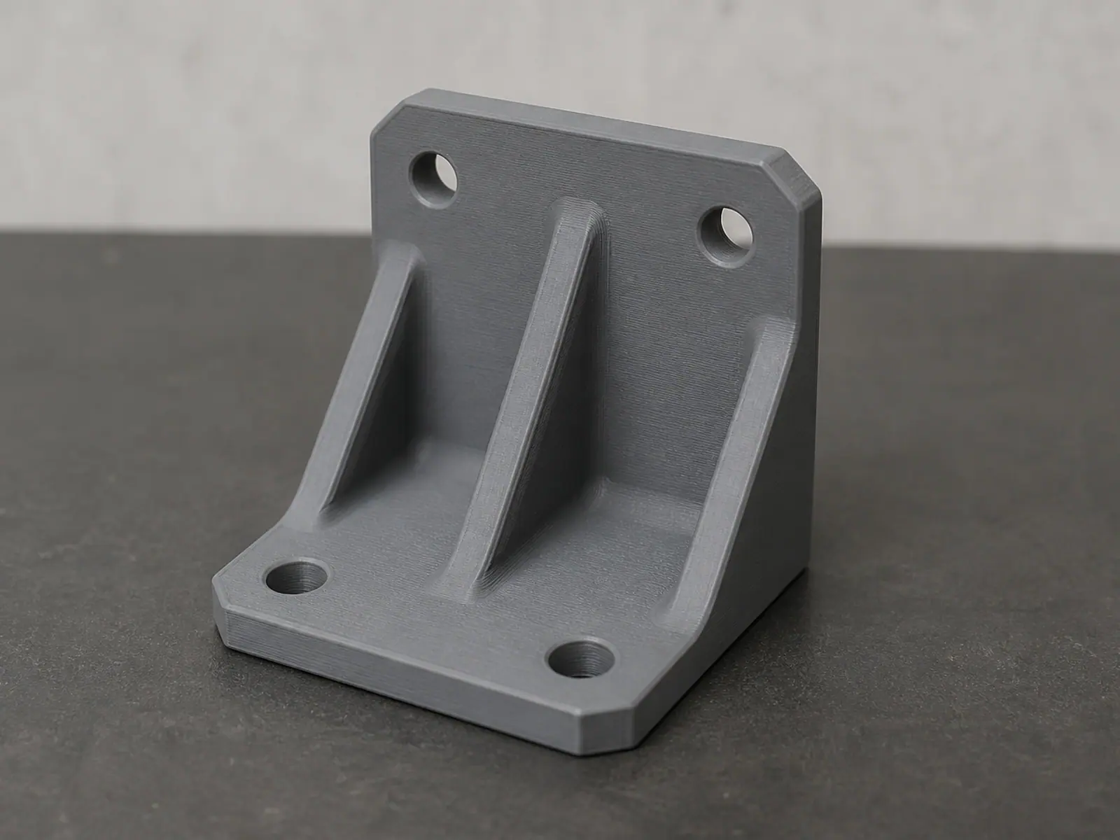
- Hole spacing on the surface it bolts to, centre to centre in both directions, plus the hole diameter.
- The thickness of the panel, post or tube it mounts to, and how much of that thickness is available for a fastener.
- The gap between the two mounting points — this sets the arm length, which sets bending load more than anything else.
- The fastener: screw size, head type, and whether there is room to turn a tool in that space.
- Clearance around the bracket in its installed position, including whatever moves past it.
- The angle between the two surfaces, if it is not a right angle. A bracket drawn at ninety degrees for a face that sits at eighty-five will not seat.
Where the strength actually comes from
Adding material is the least efficient way to make a bracket stronger, and usually the fastest way to make it heavier and slower to print. The strength comes from four features, and each of them is set from the load rather than from symmetry.
Features that decide whether a bracket holds
| Feature | What it does | How we set it |
|---|---|---|
| Rib | Carries bending load with very little material | Depth and position follow the load direction, not a mirrored left and right |
| Fillet | Removes the stress concentration at the inside corner | Radius tied to wall thickness so the corner is not the weakest point |
| Wall and boss thickness | Resists pull-out at the fastener holes | Set from the material and the screw size, with material added around the holes only |
| Hole clearance | Lets the bracket align while it is being fastened | Oversized or slotted on one axis where the mating part has its own tolerance |
Orientation, fasteners and clearances
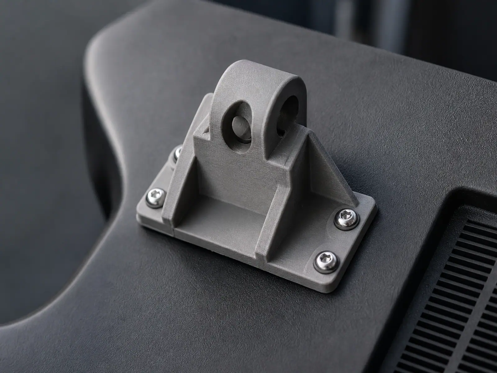
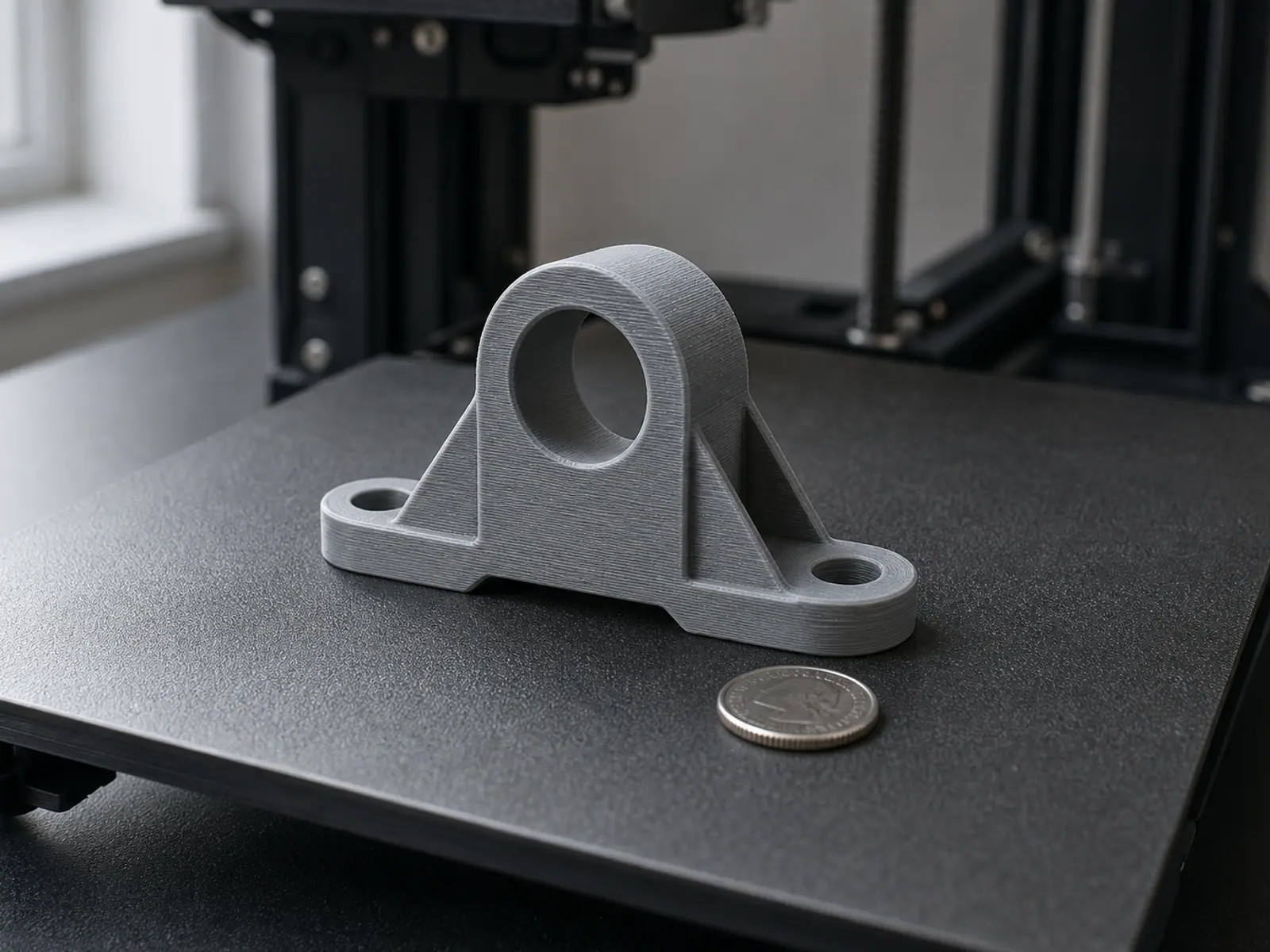
The same geometry printed flat and printed upright are two different parts. Orientation is chosen so the arm's load travels along the layers, supports land on faces that do not matter, and the layer lines do not run through the thin section at the corner where the failure would start.
- Arm loaded along the layers, never across them, even if that means cutting the print into two parts.
- Two-part designs joined with a lap joint and screws where a single print would put the load across the layer lines.
- Holes printed slightly undersized and drilled or reamed to size where a fastener needs a precise fit.
- Counterbores and recesses added so screw heads sit flush where clearance is tight.
- Support kept away from any face that has to sit flat against a panel.
- A spare allowance of material around the first hole to be fastened, since that is where assembly loads are highest.
Print one, load it, then finalise
For a bracket, a prototype is worth more than a render. Print one, bolt it in place, and put the actual load on it before we commit the geometry. If something moves, the fix is usually local — a rib deeper by a few millimetres, a fillet enlarged, a hole moved — and it is quick to change while the model is still parametric.
You receive the bracket CAD with the interface features separate from the body, plus a print-ready STL or 3MF in the orientation we recommended. If the part has to be produced in quantity later, the same model can be used for that; the modelling job does not lock you into one process. Editable CAD and prototype printing are both available as options.
Send one photo of the mounting surface with a rule in it and one of the bracket in place. Those two photos answer questions that a dimension list usually leaves open.
Related services
Frequently asked questions
Frequently asked questions
What do you need to design a custom bracket?
Is a 3D printed bracket strong enough?
Can you copy the shape of a bracket I already have?
Which direction should the bracket be printed in?
Can the bracket have slots instead of round holes?
Can you design a bracket that also holds a cable or a sensor?
Reinforcement in the Direction the Load Comes From.
A printed bracket fails for one of three reasons: the load runs across the layer lines, the ribs sit on the wrong face, or the hole pattern was measured from the wrong reference. All three are settled before the model is finished, which is why the first thing we ask for is not a shape but a load — what the bracket holds, how heavy it is, and which direction it pulls. The geometry follows from there: ribs on the side that carries tension, a fillet where the arm meets the base, and an orientation that lets the layers run along the arm instead of peeling apart across it. Send the hole pattern on the surface it bolts to, measured centre to centre, plus the thickness of the panel it mounts to and the space around it.