
Custom 3D Modeling for 3D Printing
A Case Built Around Your Board.
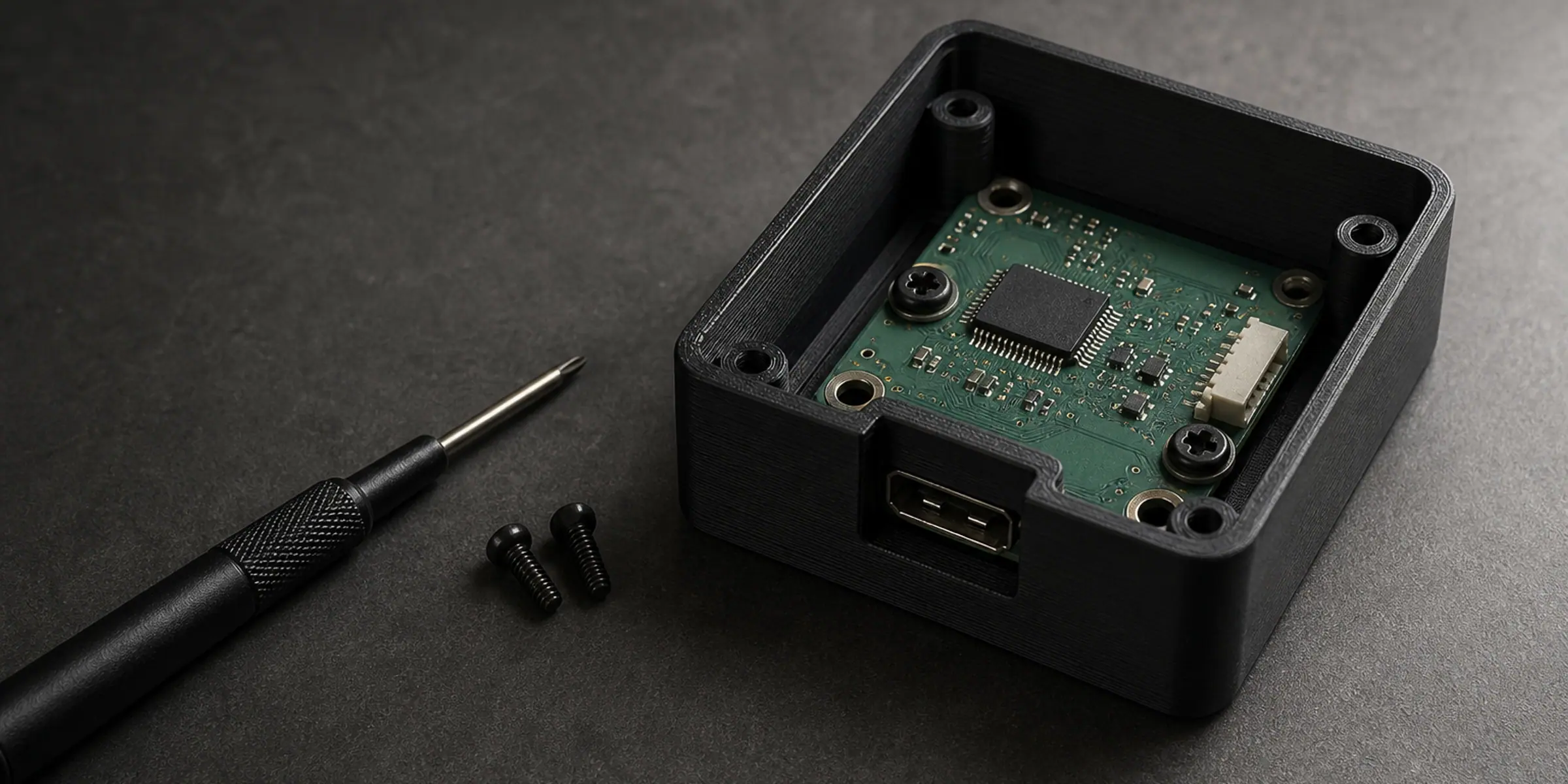
An enclosure is a set of constraints before it is a shape. The board sets the internal footprint, the connectors set the walls, the cable entry sets where the lid splits, and the heat sets the vents. Before modelling, we need the board outline and its mounting hole positions, the height of the tallest component, the position and size of every port that has to stay accessible, and how the case will be assembled — screws, clips or a sliding lid. Photos of the board with a rule across it are often faster than a drawing, because they show where each connector sits relative to the edges. If no drawing of the board exists, measured outline plus the two hole spacings are enough to start.
The board defines the case, not the other way round
A printable PCB enclosure is driven by four numbers: the board's outline, the spacing of its mounting holes, the height of the tallest component on each side of the board, and the size of the connectors that must remain reachable. Everything else — wall thickness, fillets, vents, the lid — is decided around those. When a case is designed from a drawing that ignores the board, the first print usually ends with a connector that cannot be plugged in.
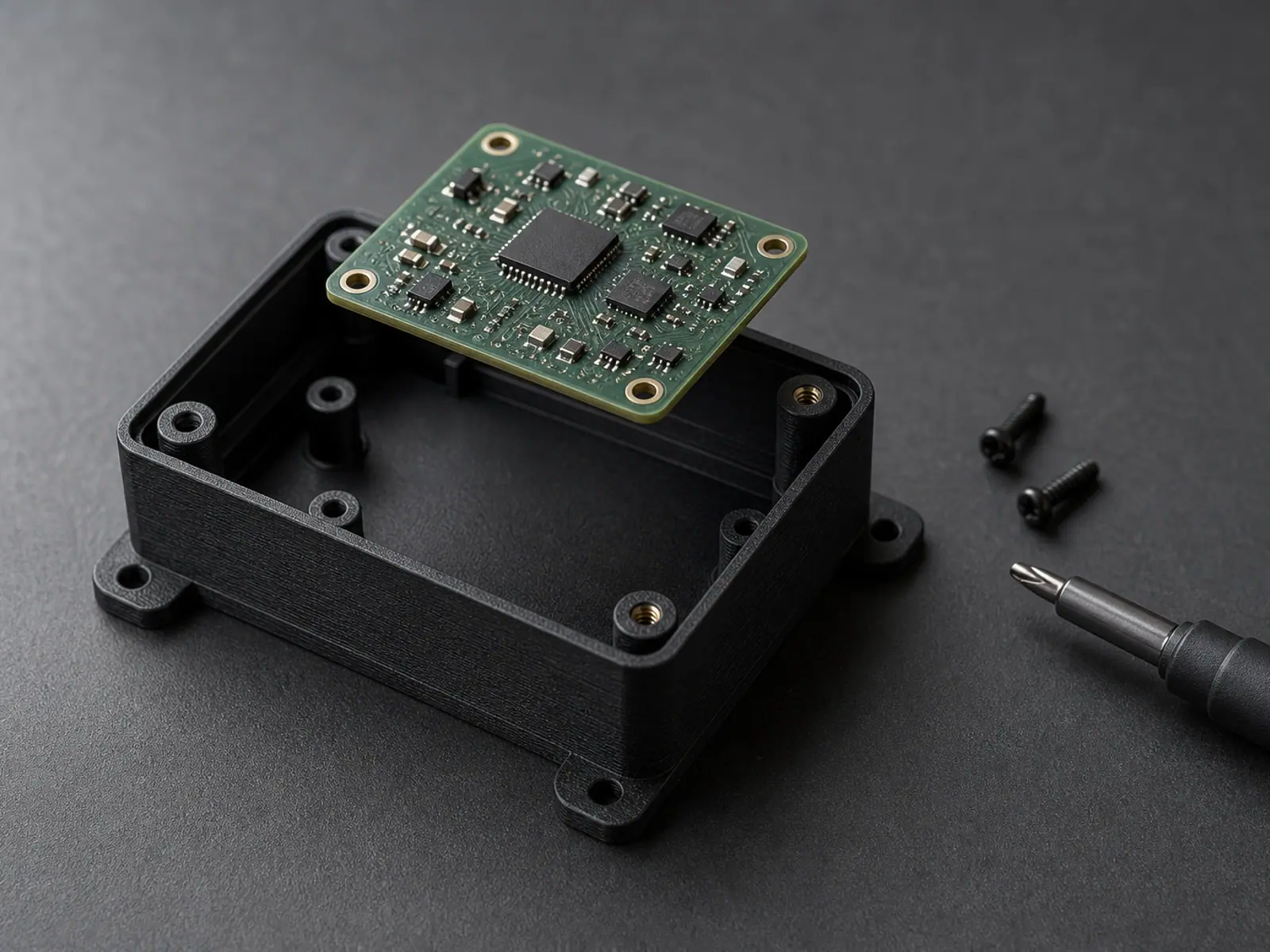
Where the board sits is therefore the first decision, not the last. Stand-offs come off the base at the same spacing as the board's holes, the board's underside clearance sets how far the base plate sits below it, and the internal height follows from the tallest component plus a small margin. Get that stack right and the rest of the case tends to fall into place.
What to measure on the board
- Board outline: length, width and thickness, measured at the widest point including any tab or notch.
- Mounting hole spacing, centre to centre, in both directions, plus the hole diameter.
- Height of the tallest part on the component side, and separately on the solder side.
- For each port: centre position along the board edge, the connector's outside dimensions, and the height of its centreline above the board.
- The cable or wire entry if one exists, and the direction it leaves the case.
- Anything that must be touched after assembly: buttons, switches, a card slot, an indicator light.
The decisions a printable enclosure has to make
Once the internal stack is fixed, the case is a short list of deliberate choices. Each one trades something off, and each one is easier to agree before modelling than to correct after printing.
Enclosure decisions and what drives them
| Decision | Options | What we need from you |
|---|---|---|
| Wall thickness | 1.6 mm to 3 mm depending on material and handling | The material, and whether the case will be handled or mounted and left alone |
| Lid | Screwed, snap-fit, or a sliding panel | How often the case has to be opened after assembly |
| Ventilation | Slots, a grille, or open sides with a partial insert | Whether anything inside produces heat, and whether dust or splash is a concern |
| Mounting | Bosses, flanges, a base plate or a rail clip | What the case is fixed to, and from which direction the fasteners go in |
Ports, lids and assembly are where printed cases fail
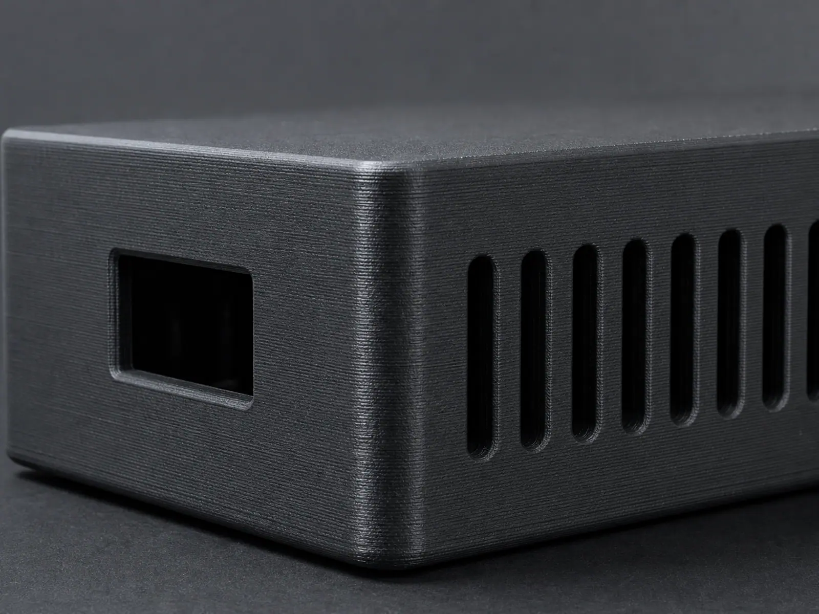
Most first prints of an enclosure work everywhere except one opening. The reasons repeat: a cut-out sized to the connector body rather than to the plug that has to pass through it, a lid that closes on a cable, or a snap-fit tab printed in the direction that breaks it. These are avoidable with a few rules applied while the model is open.
- Size every cut-out for the plug, the overmould and the cable bend radius — not for the socket on the board.
- Give each port a small internal clearance so a connector that sits a fraction of a millimetre off centre still enters.
- Split the lid so the cable entry can be closed around a terminated cable rather than threaded through a hole first.
- Orient snap-fit tabs so they bend across the layer lines, not along them, or use screws where the case gets reopened.
- Keep screw bosses at least one wall thickness from the outer surface, with a pilot hole sized for the screw being used.
- Add a small flat area for a label or a QR sticker if the product will be handled by someone else.
Model, test fit, then finalise
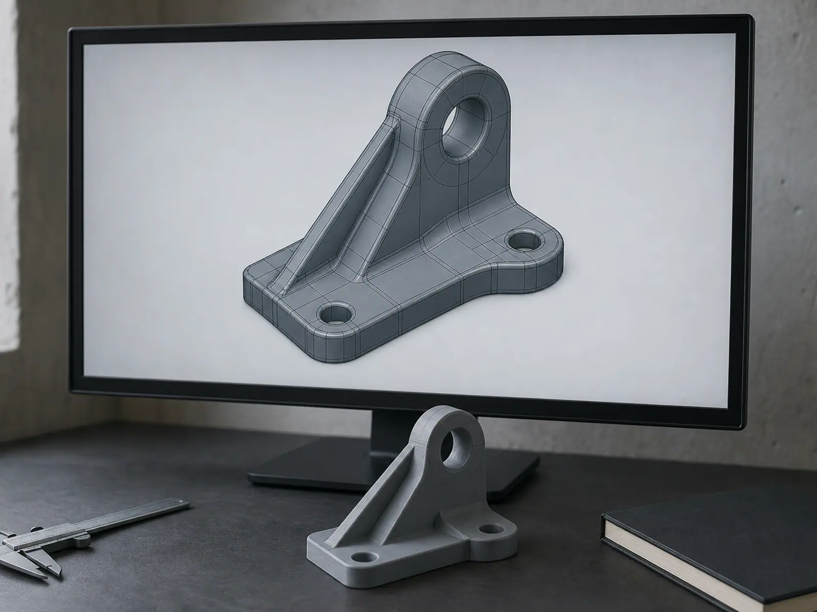
The model is delivered as enclosure CAD with the internal features separate from the shell, so a stand-off can be changed without rebuilding the whole case. From that, a print-ready STL or 3MF is exported, and the slicer settings that matter — orientation, layer height and support placement on the internal faces — are chosen before the file is handed over.
For a first enclosure, printing one and fitting the board against it is worth the time. Prototype printing is available as an optional step after the model review, and the part is revised from what the test fit shows rather than from what the screen shows. Editable CAD is available if you want to keep iterating on the case yourself.
Send a photo of the board with a rule lying across it, plus the two mounting hole spacings. That combination is usually enough to begin modelling before any formal drawing exists.
Related services
Frequently asked questions
Frequently asked questions
I do not have a drawing of my PCB. Can you still design the case?
How do I stop the case blocking a connector?
Should the lid be screwed or a snap fit?
Can the case be made to keep water or dust out?
Can you add mounting holes so it fits my equipment?
How do I handle heat inside the enclosure?
A Case Built Around Your Board.
An enclosure is a set of constraints before it is a shape. The board sets the internal footprint, the connectors set the walls, the cable entry sets where the lid splits, and the heat sets the vents. Before modelling, we need the board outline and its mounting hole positions, the height of the tallest component, the position and size of every port that has to stay accessible, and how the case will be assembled — screws, clips or a sliding lid. Photos of the board with a rule across it are often faster than a drawing, because they show where each connector sits relative to the edges. If no drawing of the board exists, measured outline plus the two hole spacings are enough to start.