
Custom 3D Modeling for 3D Printing
From a physical part to CAD you can actually edit.
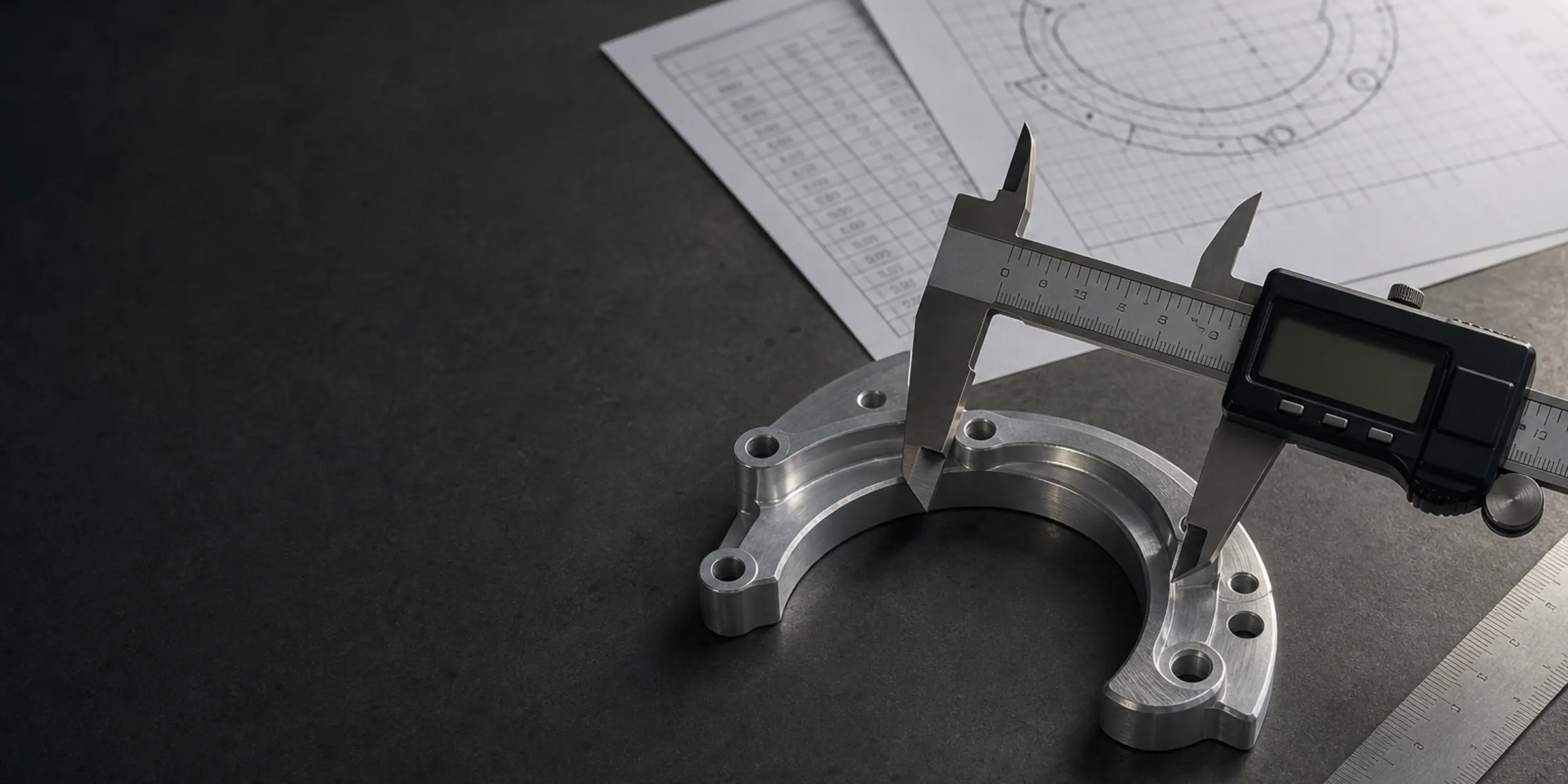
A part exists, there is no drawing, and somebody has to make it again — or improve it. The output has to be an editable solid model with real dimensions, not a mesh shell that nobody can modify. How accurate that model can be depends on the input, so we choose the method first: caliper measurement for anything that can be reached and reasoned about, scan data where the form is too organic to measure feature by feature, or a combination of the two. Then the mesh is rebuilt as recognisable CAD features — planes, cylinders, bores and real threads — so the model can be dimensioned, edited and manufactured from.
Three inputs, three different error budgets
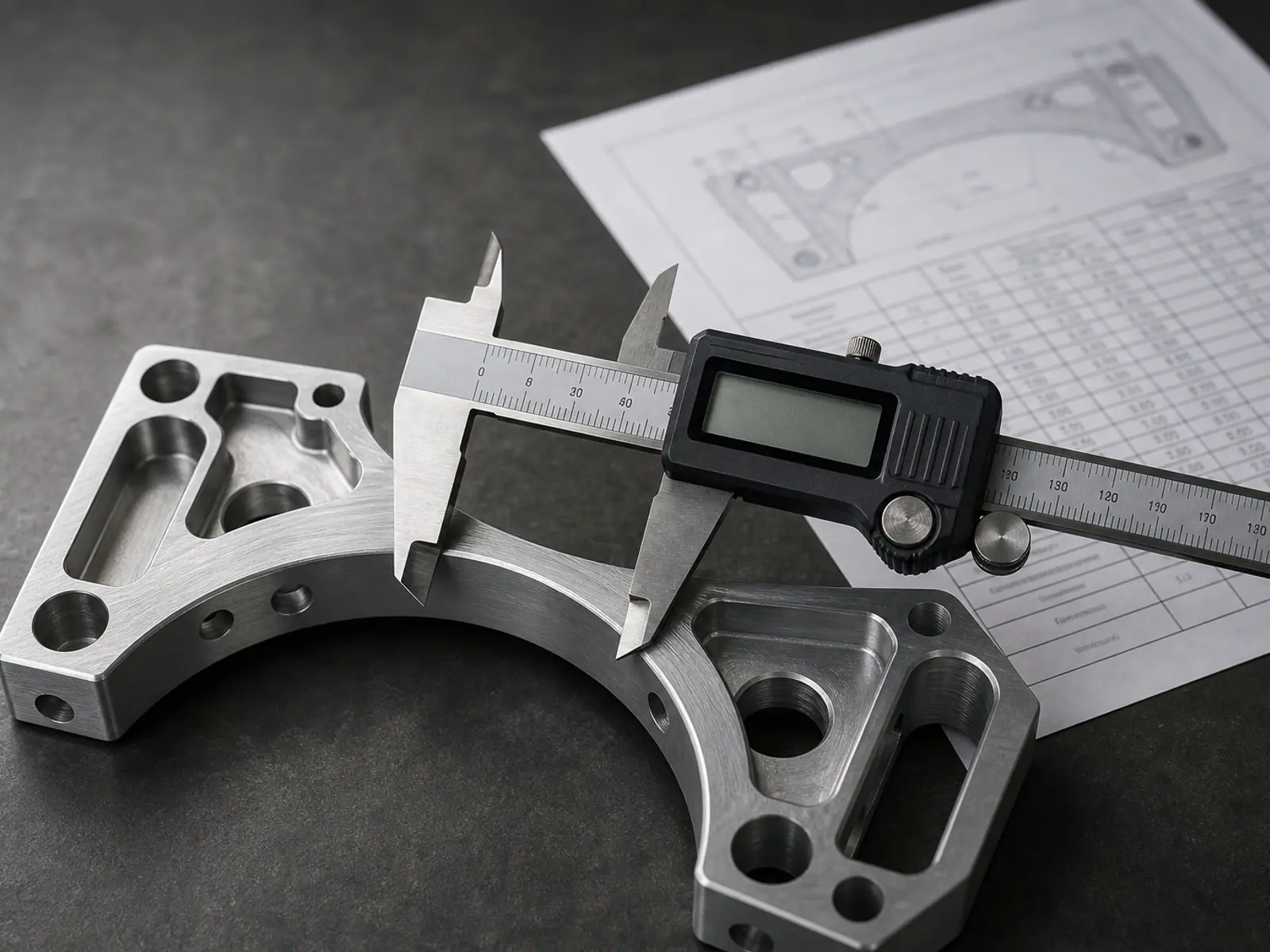
Part reverse engineering is often sold as if scanning were the accurate method and measuring were the crude one. Reality is the opposite more often than people expect. A caliper measures one dimension to a small tolerance; a scan measures millions of points to a much looser one, and the error compounds when several scans are stitched together. What decides the result is not the equipment but which surfaces matter — and those are usually flat, cylindrical or threaded surfaces that are easier to establish by measurement than by fitting.
Choosing the input is the first engineering decision, not a formality
| Input | Suits | Main source of error |
|---|---|---|
| Hand measurement | Parts with flanges, bores, holes, threads, steps and datums that can be reached with a caliper or a height gauge | Worn or corroded surfaces: you measure the part as it now is, so the original dimension has to be inferred rather than read |
| 3D scan data | Free-form surfaces, sculpted handles, airflow shapes, cast housings whose form is not reducible to a few features | Point noise, registration between scans, hidden undercuts, and surfaces that reflect, transmit or absorb the scanner's signal |
| Both, in sequence | The usual case: measured features for everything functional, the scan for the surrounding form | Reconciling two sources that disagree: the measured interface wins, and the scan is adjusted to meet it |
Where the error really comes from
Reverse engineering accuracy is set by decisions, not by the resolution written on a device. Which face is the datum, whether a bore is treated as nominal or as-scanned, whether a worn surface is restored to its original size or kept as it is — each of those moves the model more than the measuring instrument does. We agree those decisions with you before modelling, and the finished model is reported against them.
- Wear and corrosion make a real dimension unrecoverable: what you can measure is the used part, so the original size has to be inferred from how it mated.
- Thin walls, dark surfaces, clear parts and shiny parts are difficult to capture, and the failure appears as a hole or a spike in the mesh rather than an obvious error.
- Undercuts and deep pockets can be invisible to a scanner, which will bridge them as though the surface continued straight across.
- Stitching several scans introduces alignment error, so a part scanned in three sections can measure differently at each overlap.
- A mesh records a thread, a spline or a knurl as texture. Nothing in a point cloud says what the pitch is, so those features have to be measured and rebuilt as real geometry.
A scan is a picture of a surface; it is not a set of dimensions. Deciding the nominal sizes and the datums is the engineering work, and it is the part of reverse engineering that cannot be automated.
Scan to CAD: what a mesh cannot give you
A point cloud or mesh can be sliced and printed as it stands, and sometimes that is genuinely all that is needed. It cannot be dimensioned, it cannot be modified intelligently, and a hole in it will remain a hole in every copy. So the mesh is used as reference geometry, and the model is rebuilt as solids: a hole becomes a cylinder of one diameter with a position, a boss becomes a revolve or an extrusion, a face becomes a plane with a defined angle to its neighbours.
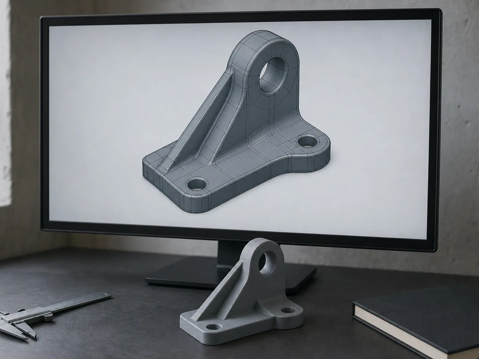
That rebuild is what makes the model editable later. If the mating part changes, a dimension changes and the model updates. If the part is to be machined, the machinist gets real circles and real planes to work to, not a triangulated approximation. It also makes inspection possible: the mesh can be overlaid on the rebuilt solids and the deviation reported on the surfaces that matter.
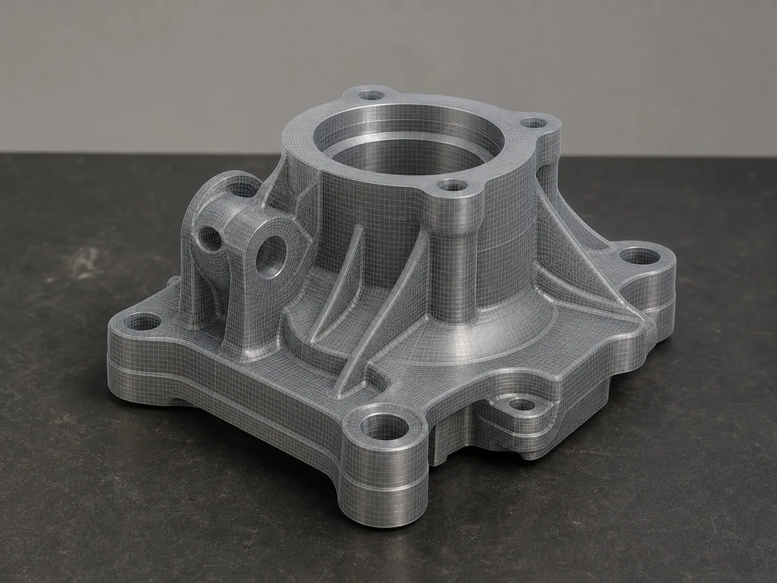
- Functional faces are rebuilt to nominal: bores, shafts, spigots, sealing faces, mounting planes.
- Decorative or organic surfaces may be kept closer to the scanned form, because there is nothing to gain from regularising them.
- Threads, splines and knurls are rebuilt as real features at measured sizes so they can be manufactured.
- The accepted tolerance is agreed per surface group, so accuracy is spent where it changes whether the part works.
What we ask before quoting a reverse engineering job
These five answers are what turn a vague enquiry into a fixed price, and they take a few minutes to write. If you already have scan data, send it and we will tell you what it can and cannot support. If you do not, we will tell you whether scanning would actually help before you spend anything on it.
- What the part does, and what would happen if the rebuilt version were slightly out: does it seal, locate, carry load or only cover?
- Which surfaces are functional and which are cosmetic, so accuracy is not spread evenly over the whole model.
- Whether this is a one-off or a part that will be re-ordered, since a repeatable part needs stable datums and a documented model.
- Which output formats are needed: STL or 3MF for printing, STEP for machining or moulding, editable CAD when you want to modify it yourself.
- Any reference for nominal size — a drawing, a specification, a mating part, or a new replacement that can be measured for comparison.
Deliverables, revisions and how the work is quoted
The deliverable is an editable solid model at 1:1 in millimetres: STEP for manufacture, STL or 3MF for printing, and the native file with its feature tree when the project includes editable CAD. Where the input was scan data, the model is delivered with a short deviation note describing how closely the rebuilt surfaces follow the measured ones, on which faces, and where the model deliberately departs from the scan to restore a nominal size.
Revisions inside the agreed tolerance are part of the job. Revision cycles are not unlimited, and a change of scope — a second part, a different interface, a change from printing to machining — is re-quoted rather than absorbed. Modelling projects start at $100; the scope above that follows the part: how many features have to be recognised, how many surfaces carry tolerance, and how much of the measurement work we have to do from what you send.
Confidential project handling applies as standard: your part, your drawings and your name stay out of our published work unless you give written permission.
Related services
Frequently asked questions
Frequently asked questions
Do I need a scan of the part to start?
How accurate can a reverse engineered model be?
Can you reverse engineer a part that is worn or damaged?
Will the model be editable, or just a mesh?
What does reverse engineering cost?
From a physical part to CAD you can actually edit.
A part exists, there is no drawing, and somebody has to make it again — or improve it. The output has to be an editable solid model with real dimensions, not a mesh shell that nobody can modify. How accurate that model can be depends on the input, so we choose the method first: caliper measurement for anything that can be reached and reasoned about, scan data where the form is too organic to measure feature by feature, or a combination of the two. Then the mesh is rebuilt as recognisable CAD features — planes, cylinders, bores and real threads — so the model can be dimensioned, edited and manufactured from.