
Custom 3D Modeling for 3D Printing
The part you measure is not the part that broke.
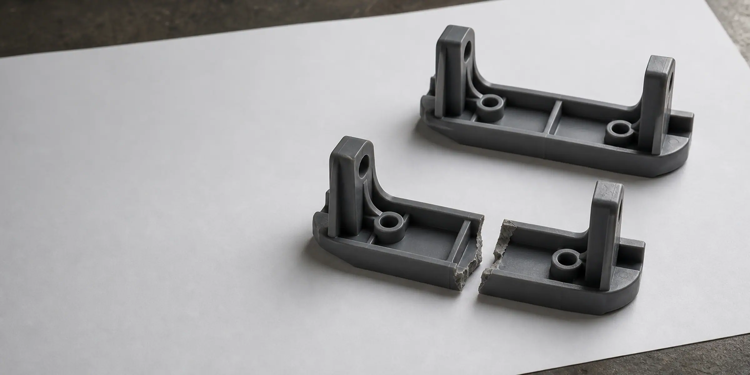
A part has failed, the machine is standing still, and nothing sells that part any more. The instinct is to copy the piece in your hand. That is the wrong reference. A broken part is not a damaged copy of a good part — it is the surviving half of a joint that failed, and the region that decides whether a replacement works is the interface it has to go back into: the bore it presses into, the shaft it clamps, the bolt spacing it picks up, the clearance the assembly needs to move. We rebuild the part as an editable solid model from those interfaces, then improve where the original failed. Send photographs of the break and the measurements you can reach.
Why the broken half cannot simply be copied
A fracture is not random. The part broke where the load concentrated and the section was weakest, so the surviving piece is missing exactly the region that mattered, and the fracture face itself is deformed: stretched, compressed, or torn away in layers. Copy the surviving half accurately and you reproduce the geometry that failed, at the wall thickness that failed, with the same sharp corner that started the crack. A replacement built that way is a countdown, not a repair.
The dimensions that decide whether the replacement works are not on the broken part at all. They are on its neighbours: the diameter of the bore it seats into, the distance between the fixing holes it bolts to, the depth of the recess, the thickness of the panel it clamps, and the clearance it needs so that the assembly still moves. That is the work. We model the replacement against the interfaces it has to return to, and only borrow the broken piece for what it can honestly tell us — the wall thickness that used to be there, the position of a boss relative to a hole, the direction the load came from.
What to measure before you send anything
You do not need to measure the broken part the way a machinist would measure a new one. You need to measure the things it has to fit against, plus enough of the original to reconstruct the wall and the positions of the features. Five minutes with a caliper and a photograph of the installed position usually settles it.
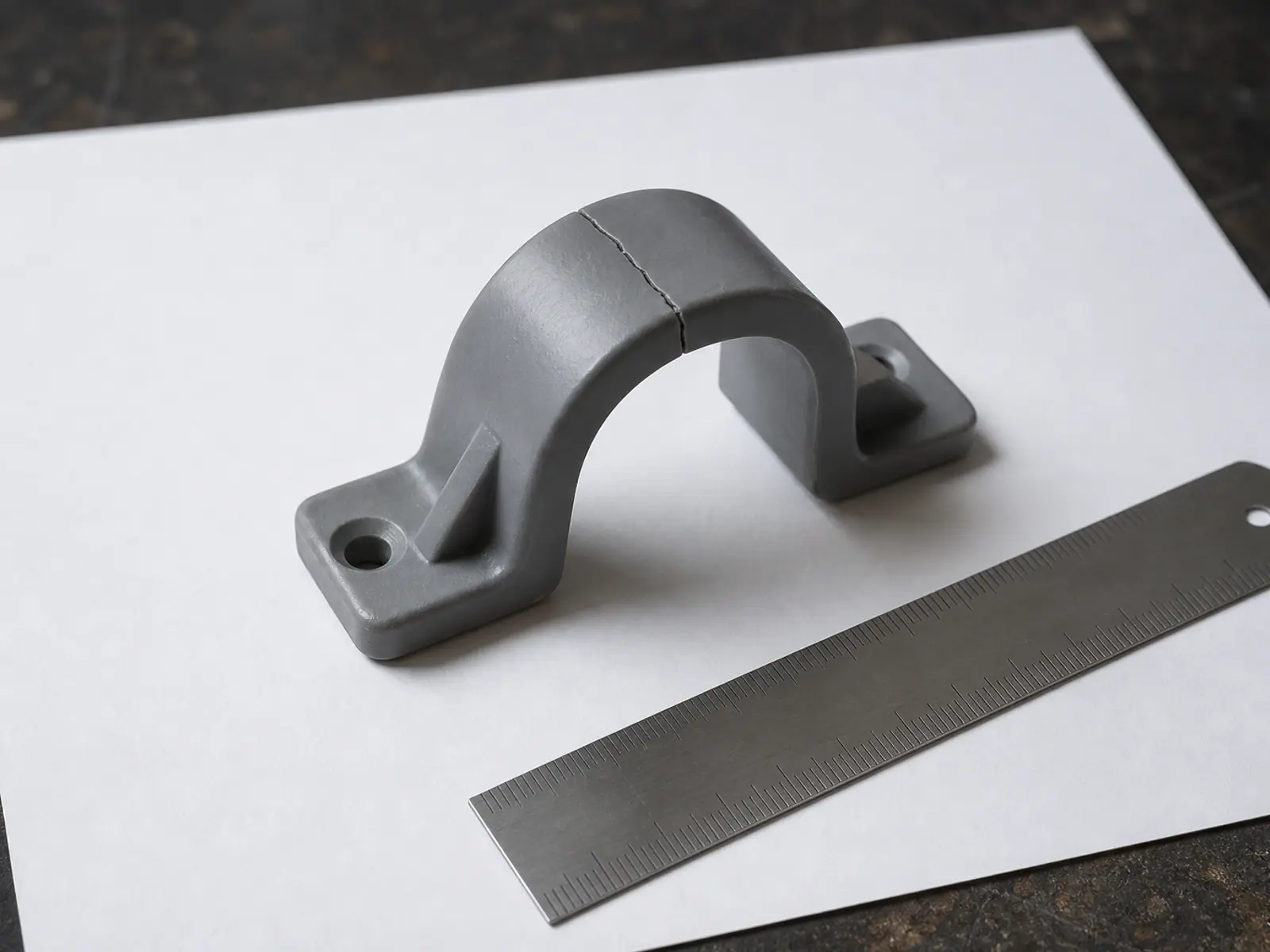
- Photograph the break: the fracture surface close up, the whole part from three angles, and the part sitting in its installed position if you can still reach it.
- Measure the interfaces: hole diameters, shaft or bore diameters, centre-to-centre distances, the length of any thread, and the depth of the recess the part seats into.
- Measure the envelope: the maximum volume the part may occupy without touching anything around it.
- Describe the failure: which way it was pushed or pulled, whether a crack was visible before it let go, and whether the material felt brittle or stretched before breaking.
- Keep every fragment, including the chips you think are too small to matter — a missing corner is often the corner that carried the fitting.
The four groups of dimensions a replacement part actually needs
| What we need | Typical measurement | Why it decides the design |
|---|---|---|
| Pressing or sliding interface | Bore or shaft diameter, length of engagement | Sets the fit: too tight and the part will not go in, too loose and it rattles and wears. |
| Fastened interface | Hole diameter, centre-to-centre spacing, panel thickness | Sets the hole pattern, the boss depth and the length of screw that can be used. |
| Seating face | Depth, step height, angle of the mating face | Sets where the part stops and how the load is transferred into the structure. |
| Clearance envelope | Free space around the part in the installed position | Allows reinforcement to be added where the original was too thin, without fouling anything. |
A replacement plastic part is not a copy of a moulded one
Most parts that break in equipment were injection moulded. Moulded plastic is solid and isotropic: it behaves the same in every direction. A printed replacement does not. It is built in layers, so it is strongest in the plane of the layers and weakest between them, and the print orientation therefore has consequences for strength that no drawing can express. We choose the orientation from the direction the load actually arrives, and we tell you which surface will face the bed and where supports will leave marks.
There are also effects that only show up in service. A part held under continuous load will creep, so a printed replacement carrying permanent tension needs more section than the moulded original, or a different geometry that puts the material in compression instead. Threads printed directly into plastic are weak and strip on the second assembly, so anything that will be opened more than once gets a heat-set insert, a captive nut or a designed clearance for a machine screw. If the original was glass-filled or fibre-reinforced, a plain filament replacement will feel floppy, and a filled material is chosen instead.
- Reinforcement is added along the load path rather than evenly, because extra wall thickness everywhere only adds weight and print time.
- Sharp inside corners from the original are replaced with fillets, since that is where printed parts and moulded parts both fail.
- Ribs and gussets are sized so they print without support where possible, which keeps the layer direction continuous through the joint.
- Where the failed part needs more strength than a printed one can give, we say so and the model is prepared for another process instead.
We take on replacement parts for equipment, fixtures, housings, covers, interior fittings, mounts and non-safety components. If a part is a safety-critical element of a vehicle or machine, that is not a job we accept — and we will tell you that in the first reply rather than quote for it.
From fragments to a fitted replacement
The sequence is deliberately short, because the expensive mistakes happen when a model is built from a photograph without anyone deciding which dimensions are real. Everything up to the test fit is a conversation about measurements.
- You send photographs, rough dimensions and a description of what the part does.
- We reply with what is missing — usually three or four specific interface measurements — and confirm the approach and price.
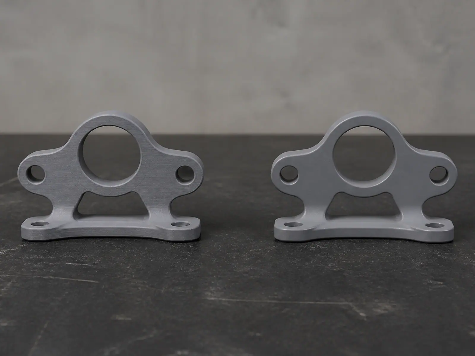
- The model is built to those interfaces as an editable solid, with the reinforcement placed where the original failed.
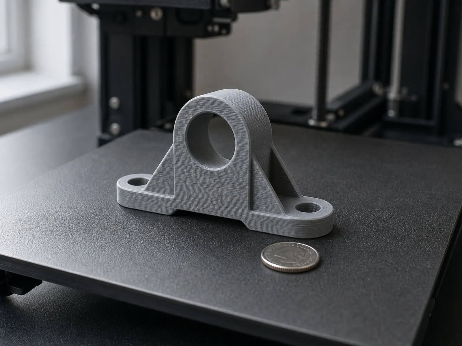
- A first print is made and test fitted, either by you on your machine or by us with optional prototype printing.
- Interference and clearance are corrected from the test fit and the final files are handed over, printed in the quantity you need.
Files, revisions and one honest limitation
You receive the print-ready STL or 3MF, a STEP file if the part may later be machined or moulded, and editable CAD with a feature tree when the project includes it. The model is watertight, dimensioned at 1:1 in millimetres, and the print orientation we recommend is documented so a later reprint matches the part that already fitted.
One limitation is worth stating plainly: a printed replacement is not a moulded original and should not be presented as an equivalent part. It is designed to do the same job in a different material and process, and where the original failed from a design weakness, the replacement is a chance to remove that weakness rather than inherit it. Modelling projects start at $100; the scope above that depends on how much of the part is missing, how many interfaces have to be established, and whether you need the part printed as well.
Confidential project handling applies to every replacement job: no part numbers, no client names and no photographs leave this studio without written permission.
Related services
Frequently asked questions
Frequently asked questions
Can you copy a broken part exactly?
What if I cannot measure anything and only have a photograph?
Do you need the physical part, or is a 3D scan enough?
Will the replacement be as strong as the original?
What does a replacement part model cost?
Can you replace parts you have never seen?
The part you measure is not the part that broke.
A part has failed, the machine is standing still, and nothing sells that part any more. The instinct is to copy the piece in your hand. That is the wrong reference. A broken part is not a damaged copy of a good part — it is the surviving half of a joint that failed, and the region that decides whether a replacement works is the interface it has to go back into: the bore it presses into, the shaft it clamps, the bolt spacing it picks up, the clearance the assembly needs to move. We rebuild the part as an editable solid model from those interfaces, then improve where the original failed. Send photographs of the break and the measurements you can reach.